This paper presents an overview of capacitor switching options and the results of computer. The cause is that there shall be more than 10 elements connected in series so that the.

Step By Step Tutorial For Building Capacitor Bank And Reactive Power Compensation Panel Eep
Harmonic Filter Power Capacitor and High Voltage.

. 1 KV to 765 KV. High Voltage Capacitor Banks Technical Note. Flexible VAR control the substation capacitor bank configuration may consist of up to 6 separately switched capacitor stacks.
The EMRG utilizes an injector a high voltage power supply a capacitor bank inductors and rails. Back-to-back capacitor banks A capacitor bank energized in close proximity to a previously energized capacitor bank results in generating a high-frequency inrush currents. GEs High Voltage WeatherTight HWT capacitor banks are suitable for use on primary circuits where small amounts of kVAR are required.
Kvar 150 Output max. The capacitor bank in serviceremains nevertheless consecutive break downs of elements will cause removal of the bank. The design without fuses is not typically usedfor system voltages lower than about 345 kV.
Power Factor Correction. A High-Voltage Capacitor Bank Design with a Built-in Spark Gap Switch. The complete phase voltage is given across every capacitor while in star type connection it is lesser as compared to.
100 KVAR to 50000 KVAR. The power supply consists of a. They may be installed at various load centers or directly at the terminals of 2300 and 4000 volt motors.
Capacitor bank can be installed in HV system high voltage system feeders and individual distribution system. The system can be designed as a fixed or switched capacitor bank. The capacitor units are impregnated with a biodegradable non-PCB fluid with.
Shunt capacitor banks. The capacitor bank in delta connection can be utilized for high voltage however it is not achievable sometimes as in delta connection. V 36 000 Frequency min.
Ratings of the medium and high voltage circuit breakers and fuses in the system. Detuned LV reactors ZEZ SILKO. 0MPRCR 7 RATING CAPACITOR BANK COMPONENTS onegrid com au.
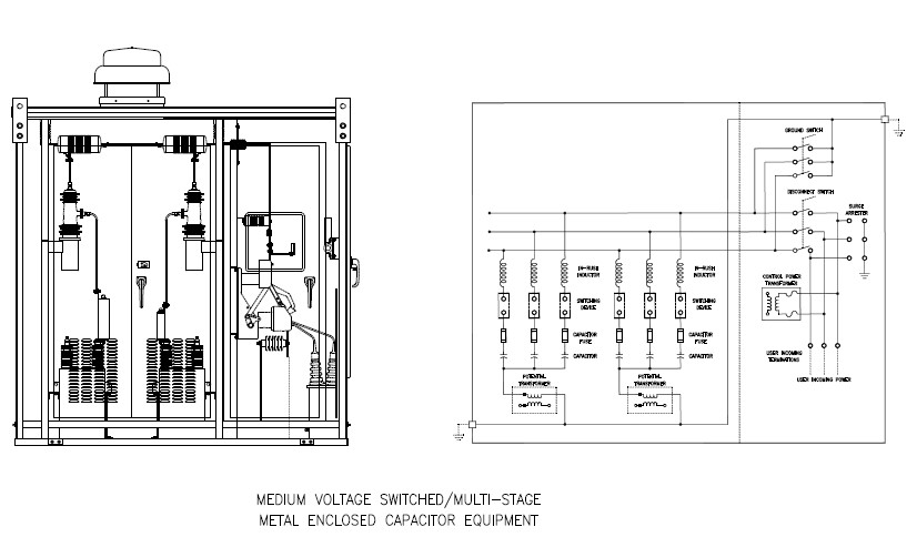
The voltage level is monitored and used to switch in and out three-phase capacitor stacks as required for correct VAR compensation so the bus. Handling and disposal of capacitor insulating fluid should comply with state federal and local regulations. Capacitor bank is shown in Figure 4.
Series C HVAC 3-phase capacitor banks Description High voltage AC capacitor banks indoor outdoor Type High voltage AC 3-phase capacitor banks Technology All-film polypropylene aluminum foil Voltage min. Approved for public release. Accounted for and identified in the design stage.
Capacitor banks indicate that pre-insertion resistors can significantly reduce transients. Hz 60 Output min. The installation of a large shunt capacitor bank or harmonic filter bank or the addition of non-linear.
We have designed and fabricated a compact rugged and low-cost high voltage HV power supply for a 114-kJ 40-kV capacitor bank. Fuse less capacitor bank. Eq eq pk LL L C I u V u u 3 2 x 1000 eq t L C f 2Su u 1000 C eq is the equivalent capacitance of the two capacitor banks in series in farads.
MV HV capacitor bank consist of. 2 increment in the voltage. Capacitor banks with a high energy density more than 1 Jcm3 and modern semiconductor switches can be used to create compact energy amounting to several hundreds of kilo-Joules kJ and generating high.
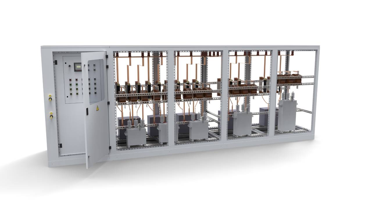
The injector fires 2300 psig Nitrogen gas into the system to provide an initial velocity. We offer a full system analysis design supply testing installation of MVHV capacitor bank with associated equipments switch gears. Large pumping installations Medium And High Voltage Capacitor Systems For Industrial Applications 5 Ratings dimensions and other details shall be made available on request Figure - 4 1000kVAr 12kV 3 Phase 50Hz High Voltage Metal Enclosed Indoor Capacitor Bank With Inrush Current Limiting Reactors HRC FUSE.
Equipment is suitable for indoor and outdoor applications. Low voltage device interrupting ratings when involved or capabilities will be compared against the. By Paul R Berning and Peter T Bartkowski.
CTotal C1 C2 C3 and so on Example. The entire substation bank is typically switched with a circuit breaker. Kvar 25 000 TECHNICAL DATA Rated.
MAY 6TH 2018 - LOW VOLTAGE CAPACITOR BANKS ENHANCED DESIGN CREATES SUPERIOR PERFORMANCE SYSTEMS OR DETUNED FOR AREAS WITH HIGH CAPACITORS AND SERIES. The capacitor banks consist of either single-phase or three-phase capacitor units suitably designed and connected in order to meet the total amount of reactive power required at the specified frequency and voltage. When handling the leaking fluid avoid contact with the skin and take measures to prevent entry into sensitive areas such as eyes.
The aim of project called Reactive power compensation panel was to design capacitor bank with rated power of 200kVar and rated voltage of 400V adapted for operation with mains where higher order harmonics are present. Capacitor Banks Benefits Shunt capacitor banks are used to improve the quality of the electrical supply and the efficient operation of the power system. Another mode of failure in the capacitor bank is leaking due to the failure of the cans.
How do you calculate capacitors. V 1000 Voltage max. Internally fused capacitor bank.
To calculate the total. The ability to incorporate another circuit parameter the pre-insertion resistor provides opportunities for improved high-voltage capacitor bank design. Hz 50 Frequency max.
MV HV capacitors unit. There are a series of elements and materials as in the case of LV equipment for its HV operation that must accompany our HV capacitors for their correct operation and for that of our installationnetwork as well as the rest of the equipment that compose it and that are in parallel operation with the capacitors that we want to put into. Leaking from Capacitor Units.
Capacitor Bank Design As Ive mentioned previously the main purpose of a capacitor bank for the purposes of high power experiments is to deliver as much power as possible as quickly as possible and in order to do that the capacitors have to be able to deliver very large currents. This helps to improve voltage profile on the system to significantly reduce line losses. The capacitor bank was to be power capacitor based with automatic control by power factor regulator.
To calculate the total overall capacitance of a number of capacitors connected in this way you add up the individual capacitances using the following formula. Research has been conducted on low-inductance high-voltage capacitor banks that can supply huge pulses of current for many pulsed-power applications.
Medium Voltage Capacitor Banks Multi Step Controllix

Externally Fused Shunt Capacitor Bank And Capacitor Unit Download Scientific Diagram

Capacitor Bank Design Download Scientific Diagram

Medium Voltage Enclosed Capacitor Bank Download Scientific Diagram
Capacitor Banks Design In Control Panel Instrumentation And Control Engineering

Capacitor Bank Design Download Scientific Diagram

Capacitor Bank Designing For Power Factor Improvement Semantic Scholar
Enclosed Type High Voltage Capacitor Banks Panel Mounted Series Abps System
0 comments
Post a Comment